
5 Common CAD Mistakes Even Experienced Designers Make (and How to Avoid Them)
- Benjamin Cabrera
- Aug 8, 2025
- 5 min read


Have you ever spent hours meticulously crafting a CAD model, only to have it cause headaches down the line during prototyping or manufacturing? You're not alone. The path from a great idea to a flawless physical product is often riddled with unforeseen challenges, and sometimes, the very tools we rely on—CAD software—can be the source of these issues. Even for experienced designers, it's easy to fall into traps that can lead to costly errors, production delays, and frustrating rework.
The truth is, you don't have to be an expert in every facet of design and manufacturing to succeed. The key is to know when to seek help. This post will explore five common CAD mistakes that can hinder your workflow and compromise your design's integrity. We'll show you not only what these mistakes are, but also how to avoid them. By the end of this article, you'll have a clearer understanding of how to streamline your design process, ensuring your CAD models are not just visually appealing, but also robust, efficient, and ready for real-world application.
The Core Problem: The Disconnect Between Design and Production
The true frustration for a mechanical designer often arises when a "perfect" digital model doesn't translate seamlessly to the real world. This disconnect can manifest in various ways: a part that's impossible to machine without multiple setups, a tolerance stack-up that causes assembly failure, or a design that simply costs too much to produce. People often feel that if they don't know how to do something, they have to fake it or it prevents them from trying altogether. But you might be surprised what you can accomplish when you delegate and team up with the right people or resources. It's about knowing your limitations
and focusing on your strengths, while bringing in expertise where you need it.
The Solution / Key Insights
Here are five common CAD mistakes and actionable strategies to avoid them:
Mistake #1: Ignoring the Importance of a Clean Feature Tree

A messy feature tree with unorganized, un-named, and redundant features is more than just a pet peeve—it's a liability. It makes the model difficult for others (or even your future self) to understand, modify, or troubleshoot. You can use AI or watch videos to learn just enough to improve your feature tree management, enabling your next design step.
How to Avoid It: Adopt a systematic approach. Name your features and sketches clearly (e.g., Main_Extrusion, Mounting_Hole_Pattern). Use folders or groups to organize related features. Suppress and review features that are not critical for your final part geometry. This will improve readability and make it easier to trace design intent.
Mistake #2: Not Designing for Manufacturing (DFM) from the Start

Designing complex undercuts, impossibly tight tolerances, or sharp internal corners might look good on screen, but they can significantly increase manufacturing costs and lead times, or even make a part un-machinable.
How to Avoid It: Think like a machinist, sheet metal fabricator, or welder as you design. Incorporate standard radii for milling tools, ensure adequate draft angles for molded parts, and use standard stock sizes where possible. A simple change in geometry can save hours of machining time and thousands of dollars in tooling costs. For more on this topic, check out this great article on Machining Square Inside Corners from Make It From Metal.
Mistake #3: Over-Constraining and Under-Constraining Sketches
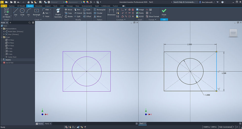
An under-constrained sketch is unstable and can change unexpectedly, while an over-constrained sketch can lead to conflicts and errors when a design needs to be updated. Both are ticking time bombs for future design changes. You can use AI or watch videos to learn just enough about sketching to take your design to the next level.
How to Avoid It: Strive for fully defined sketches. Use dimensions and geometric relations (like concentric, tangent, or parallel) to lock down all geometry. Utilize a well-thought-out plan to ensure your sketches are robust yet flexible enough for modifications down the line.
Mistake #4: Not Using Configurations or Design Tables for Part Families

If you have a series of parts that are similar but vary in specific dimensions (e.g., different lengths of a bracket), creating a separate file for each one is inefficient and difficult to manage.
How to Avoid It: Leverage configurations or design tables. This allows you to manage multiple variations of a single part within one file, making it easy to generate different sizes, control BOMs, and ensure consistency across your product family.

Mistake #5: Forgetting to Check for Interference or Collisions in Assemblies

This is one of the most common and costly mistakes. Designing parts in isolation and assuming they will fit together perfectly in an assembly can lead to major headaches during physical assembly.
How to Avoid It: Make use of your CAD software's built-in interference detection tools. Regularly run these checks as you build your assembly. This proactive step can identify and resolve clashes between components long before they become a physical problem on the assembly floor.
By avoiding these common mistakes, you can drastically improve your workflow and the quality of your designs. Imagine reducing your prototyping costs by 20%, cutting down your design revision cycles, and getting your product to market faster. These aren't just abstract benefits; they directly impact your project timelines and profitability. A clean, robust, and well-thought-out CAD model is a valuable asset that streamlines communication with fabricators, reduces errors, and ultimately helps you achieve your business goals.
Mastering these nuances of CAD is what separates a good designer from a great one. It's about looking beyond the digital model and understanding its real-world implications. If you're looking to accelerate your design process and ensure your ideas are realized efficiently and cost-effectively, it's time to work with a partner who speaks both the language of design and manufacturing fluently.
Contact us at sales@cabcad-dd.com to start the consultation on your project!


Comments